Digital Logic Chapter 6 - Registers and Counters
Digital Logic Chapter 6 - Register and Counters
Various types of registers
Register and Counters
Register
A group of binary cells (FFs) suitable for holding binary data information
In addition to the FFs, a register may have combinational gates to control when and how the new information is transferred into the register (MUXes, …).
Counter
A register that goes through a predetermined sequence of states upon the application of input pulses
The gates in a counter are connected in such a way as to produce a pre-described sequence of binary states in the register (arithmetic circuits).
Shift Register
Register: bitwise extension of a FF.
The shift register permits the stored data to move from a particular location to some other location within the register. All the n FFs are driven by the common clock signal. Sometimes with load control
Type: Based on input & output
Serial-in to Serial-out (SISO)
Serial-in to Parallel-out (SIPO)
Parallel-in to Serial-out (PISO)
Parallel-in to Parallel-out (PIPO)
Direction
Left shift, Right shift, Rotate (right or left), Bidirectional
Universal shift register
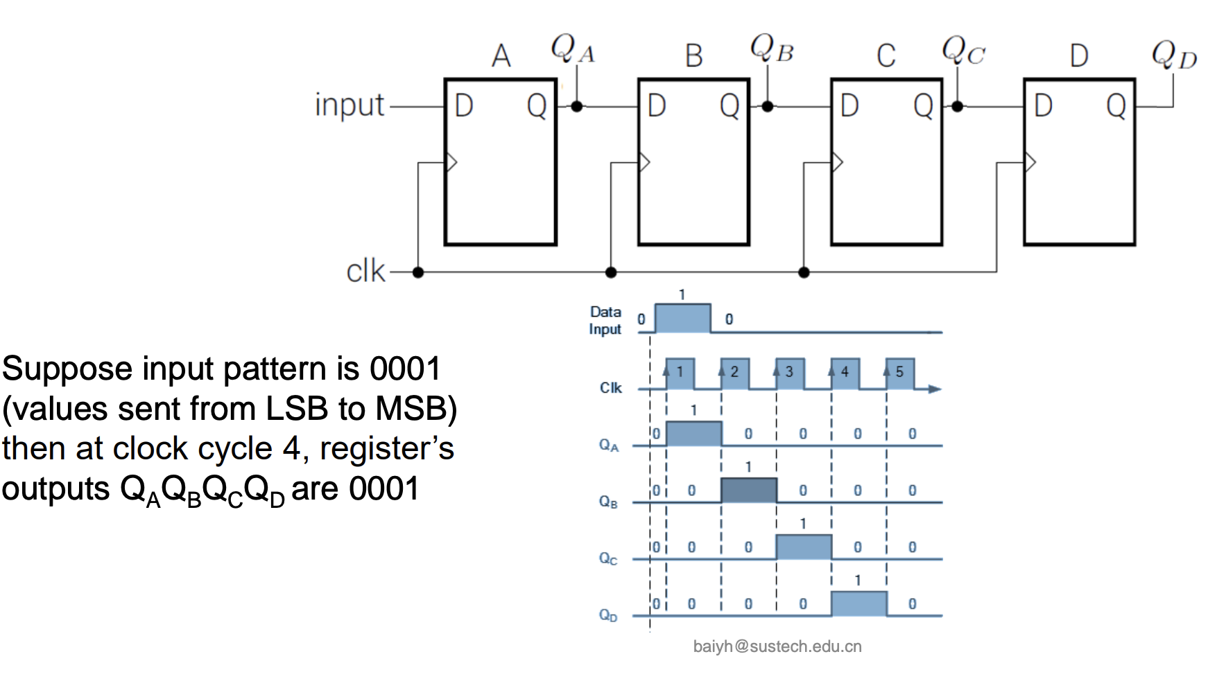
4-bit Serial-in to Serial-out
SISO: the data is shifted serially “IN” and “OUT” of the register, one bit at a time in either a left or right direction under clock control.


4-bit Serial-in to Parallel-out
SIPO: the register is loaded with serial data, one bit at a time, with the stored data being available at the output in parallel form.
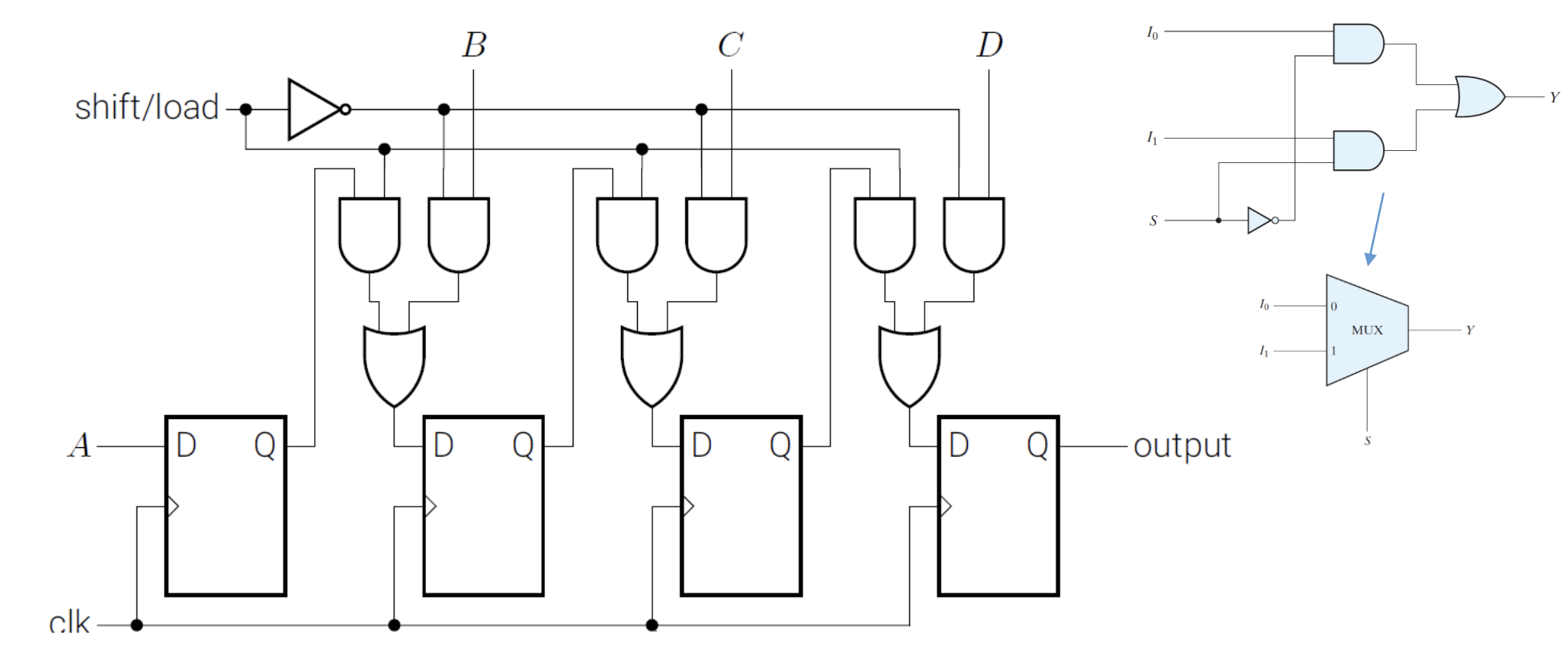
4-bit Parallel-in to Serial-out
PISO: the parallel data is loaded into the register simultaneously and is shifted out of the register serially one bit at a time under clock control.
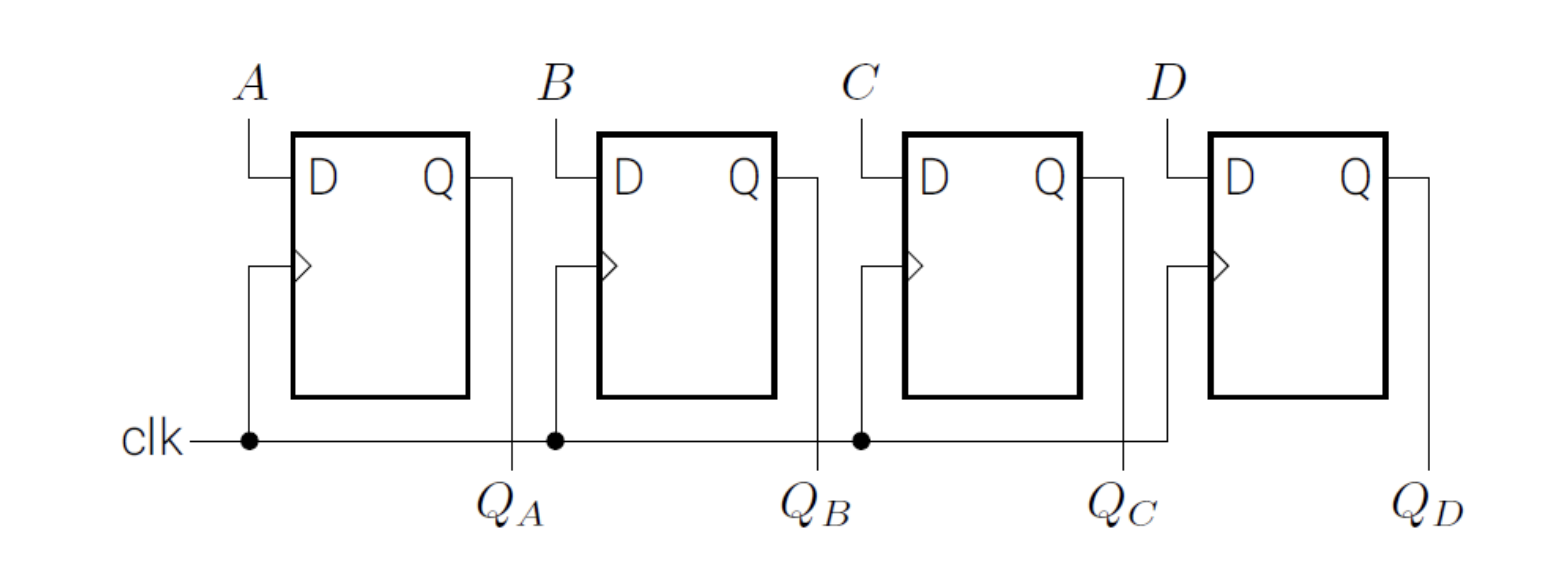
4-bit Parallel-in to Parallel-out
PIPO: the parallel data is loaded simultaneously into the register, and transferred together to their respective outputs by the same clock pulse.
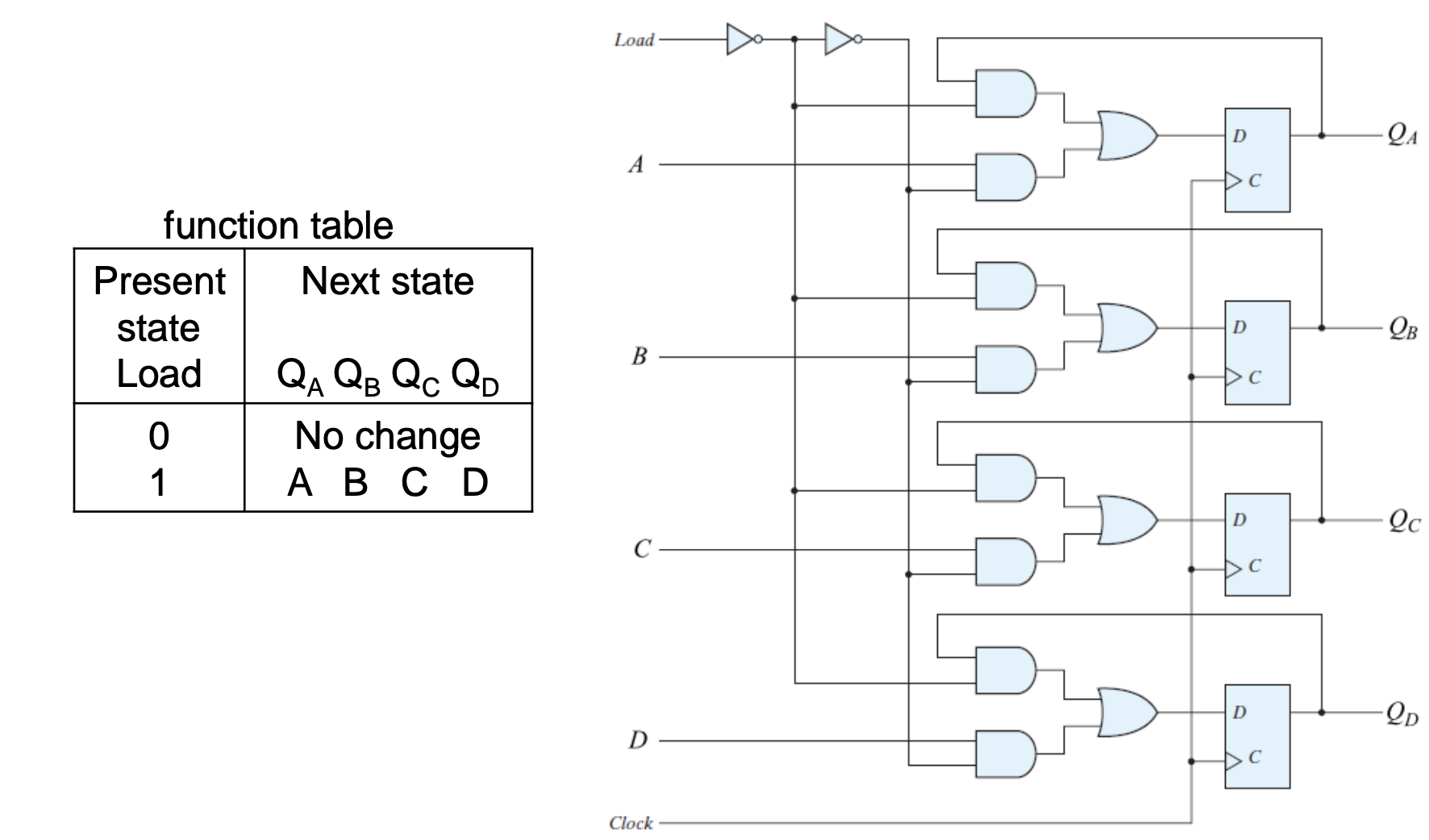
if with with Parallel Load Logic diagram
Universal Shift Register
Universal shift register : Capable of both-direction shifting and parallel load/out
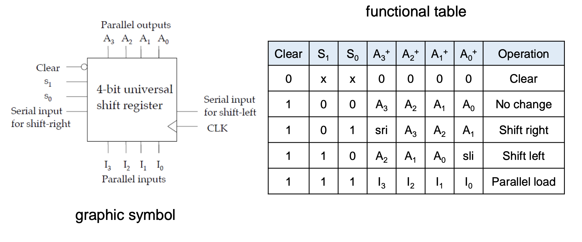
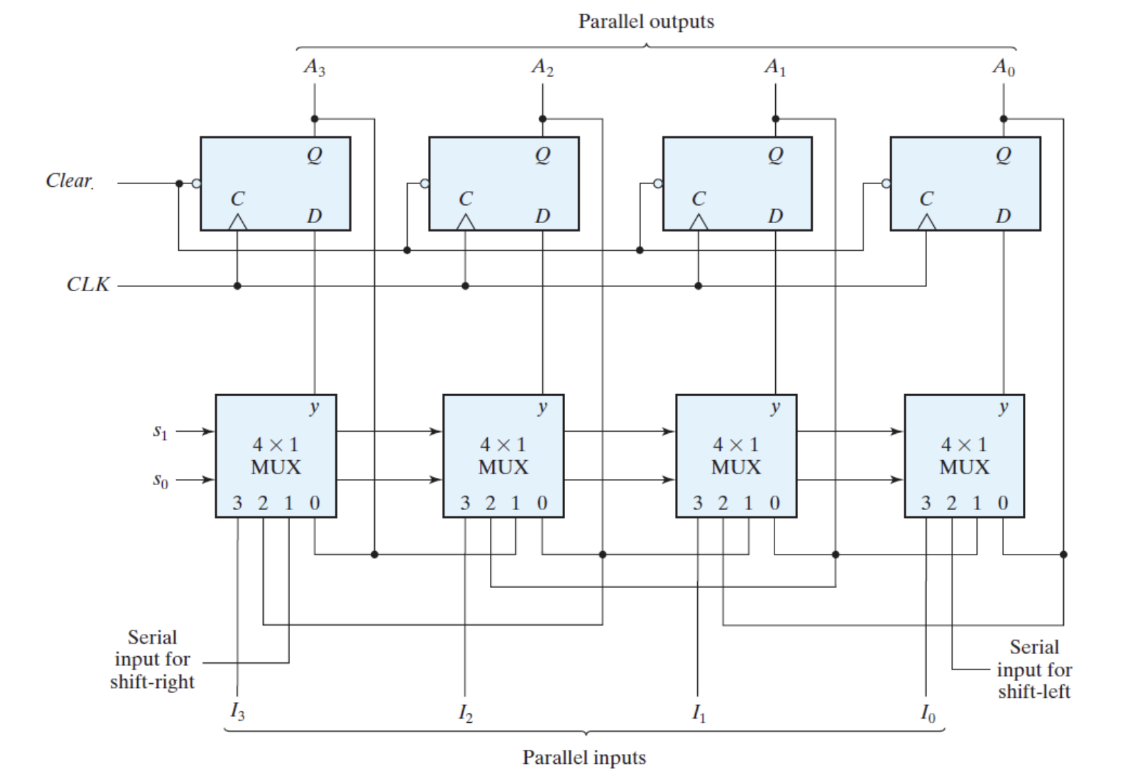
| $S_1$ | $S_0$ | operation |
|---|---|---|
| 0 | 0 | no change |
| 0 | 1 | right shift |
| 1 | 0 | left shift |
| 1 | 1 | parallel inputs |
Serial/Parallel Transfer
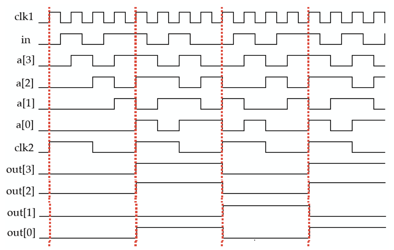
Shifters are useful in serializers and deserialisers that convert data from parallel to serial form and back again
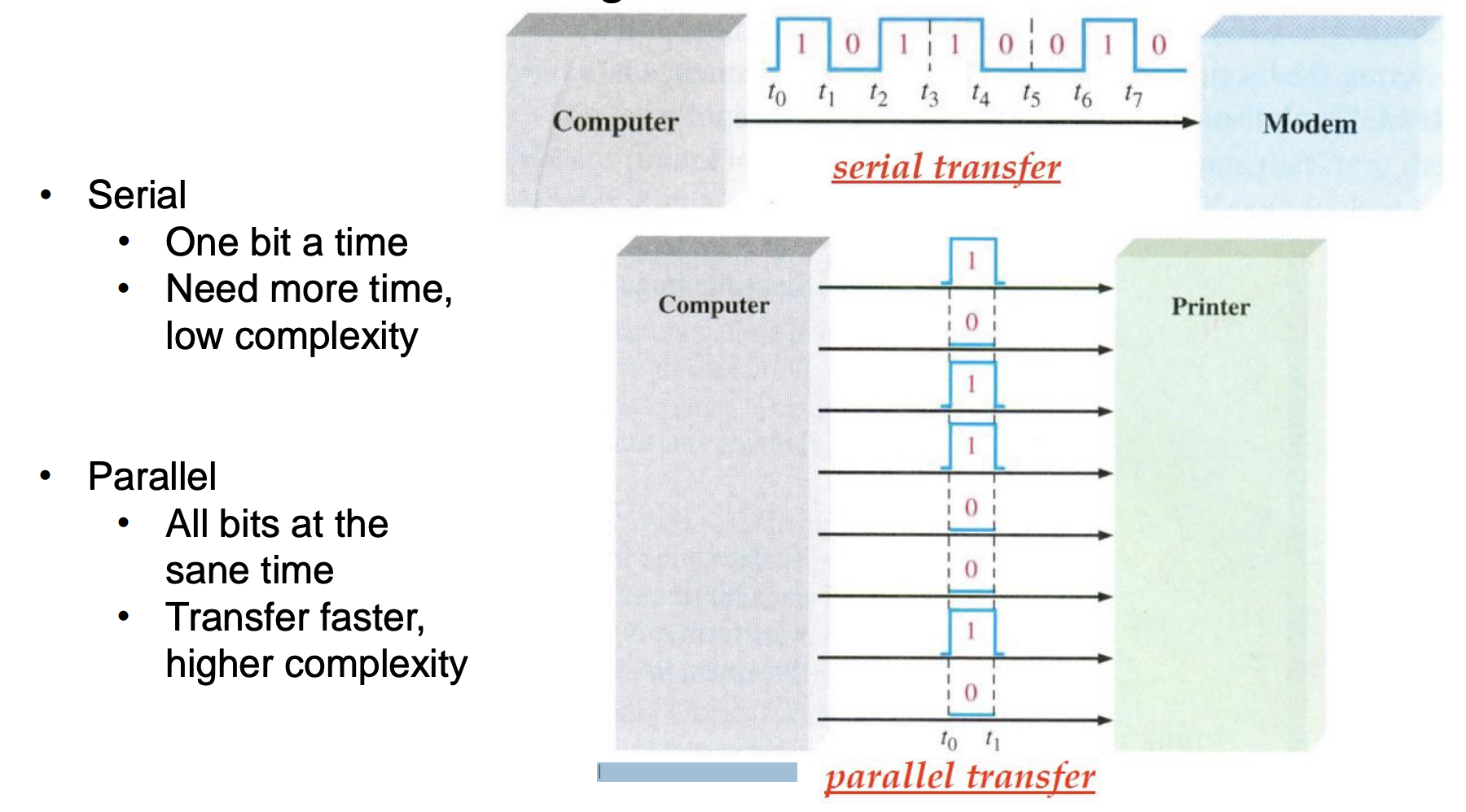
Serial to Parallel Converter
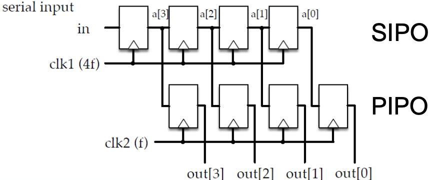
clk for SIPO is faster!
Sequence generator with shift register
Sequence Generator
A sequence generator is a circuit that generates a desired sequence of bits in synchronization with a clock.
Can be used as a random bit generator, code generator, and prescribed period generator.
The output of the combinational circuit is a function of the shift register state and is connected to the serial input of the shift register.
n FFs can generate a sequence with the length of $N <= 2^n – 1$
The required sequence can be obtained from the output of any FF, or the output of the combinational circuit.
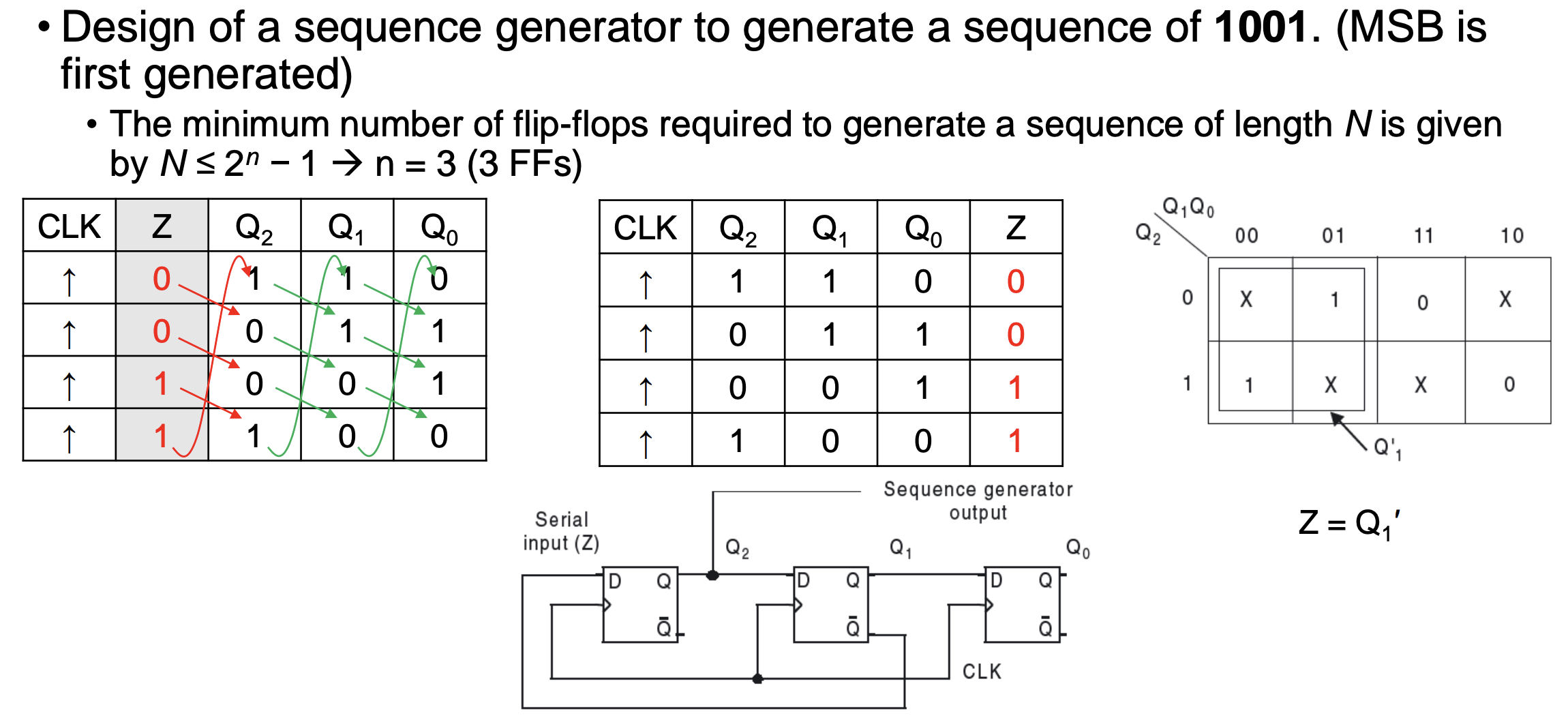
Example: Design a 4-bit Sequence Generator
Design of a sequence generator to generate a sequence of 1001. (MSB is first generated).
Noted all zero’s state is excluded to avoid that circuit being stuck in this state.
If a state occurs more than once in {$Qn,Q{n-1},…,Q_1$}, it means we need more FFs to complete the task.
Asychronous counter
Aka Serial or ripple counters
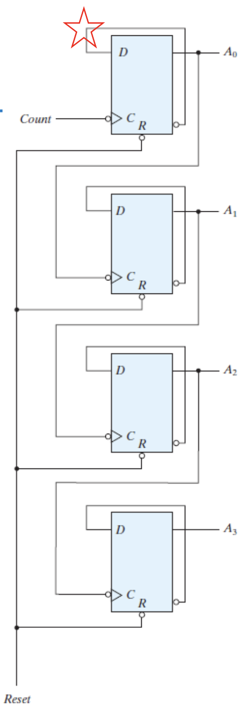
All the flip-flops are not driven by the same clock pulse.
The successive flip-flop is triggered by the output of the previous flip-flop.
Hence the counter has cumulative settling time, which limits its speed of operation.
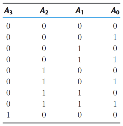
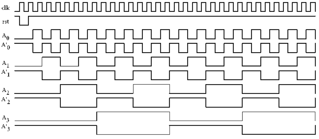
4-bit Binary Ripple Counter
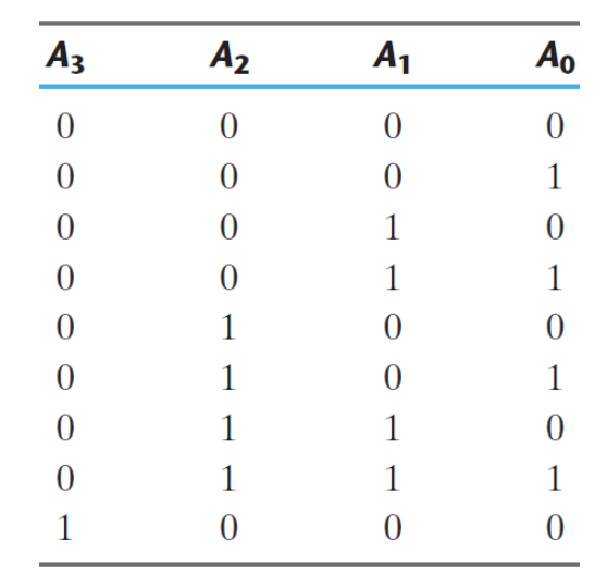
Binary Up count sequence
Timing diagram
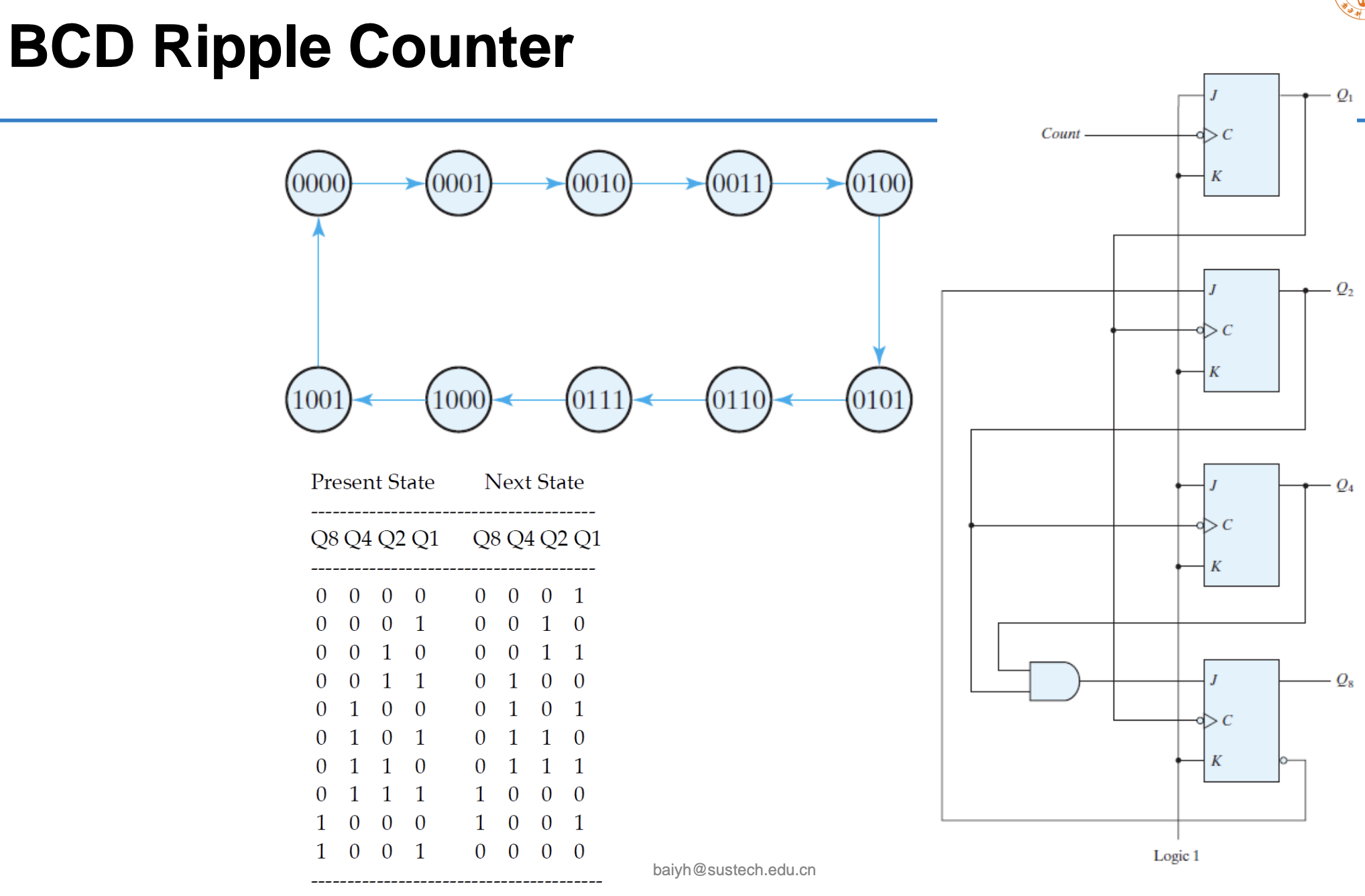
BCD ripple counter
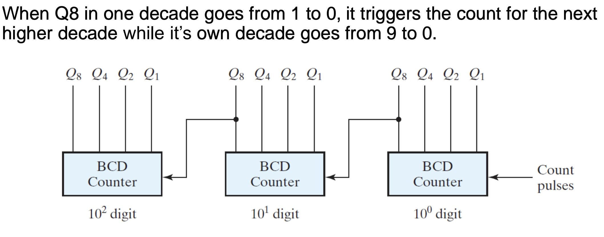
Three-decade BCD Ripple Counter
Synchronous counter
The ripple or asynchronous counter is the simplest to build, but its highest operating frequency is limited because of ripple action: delay time, glitches
Both of these problems can be overcome, if all the flip-flops are clocked synchronously.
The resulting circuit is known as a synchronous counter
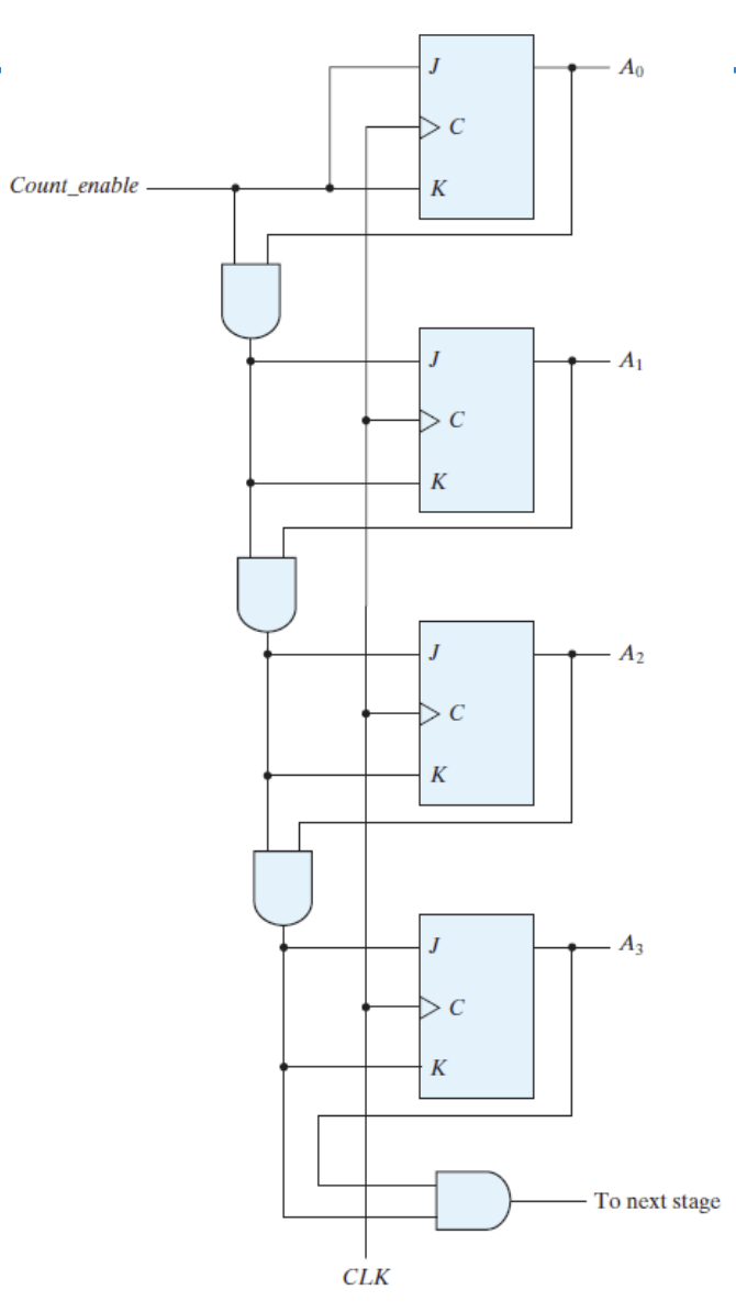
4-bit Synchronous Binary Counters
Count up: As the number of stages increases, the number of AND gates also increases, along with the number of inputs for each of those AND gates.
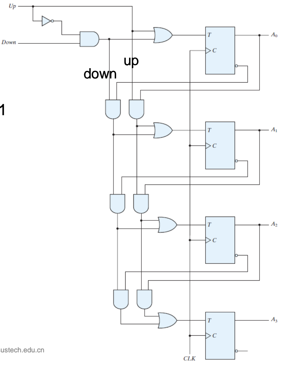
4-bit Up/Down Binary Counter
up=1, down=0 -> up count
0000,0001,…
up=0, down=1 -> down count
1111,1110,…
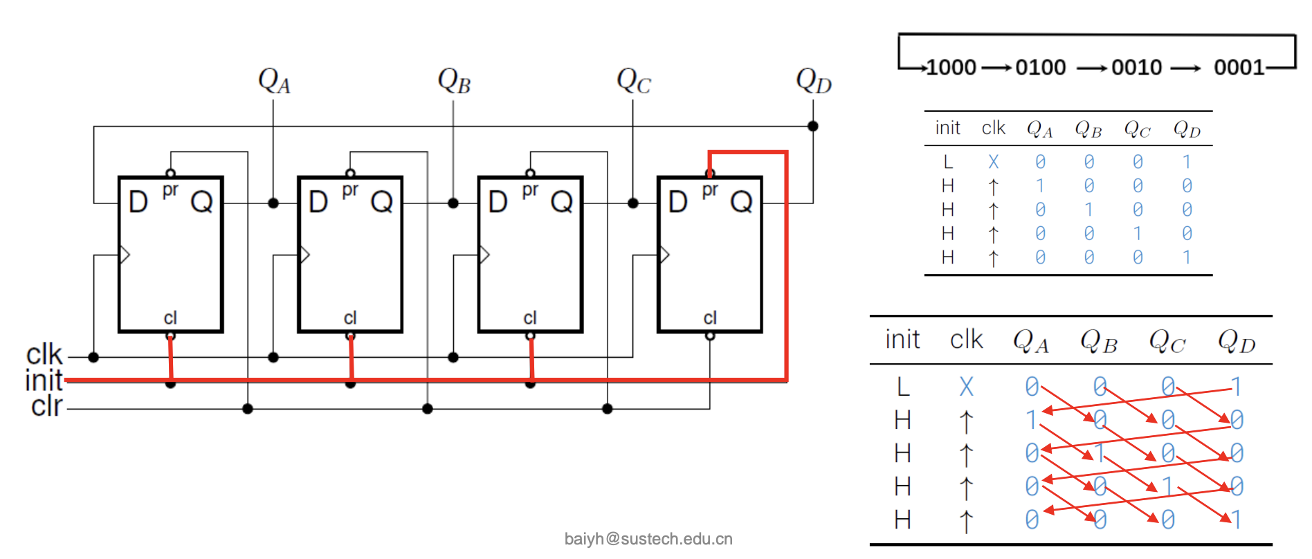
Shift Register counter
Ring Counter
A circular shift register with only one flip-flop being set at any particular time, all others are cleared. (initial value 0001 as in example)
The single bit is shifted from one flip-flop to the next to produce the sequence of timing signals.
Johnson counter
Switch-tail ring counter: a circular shift register with its complement output of the last flip-flop connected to the input of the first flip-flop
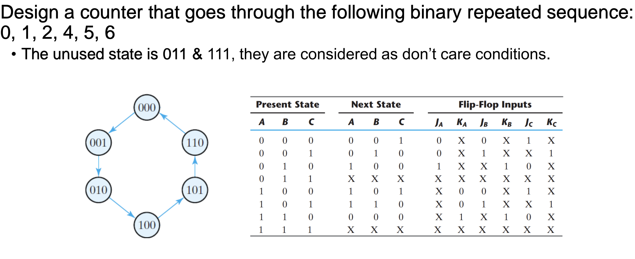
Design a synchronous counter
Recall: Design Procedure of Sequential Circuits
- Specification: design description or timing diagram
- Formulation: develop state diagram
- Generate next-state table in form of count sequence
- Choose type of Flip-Flop
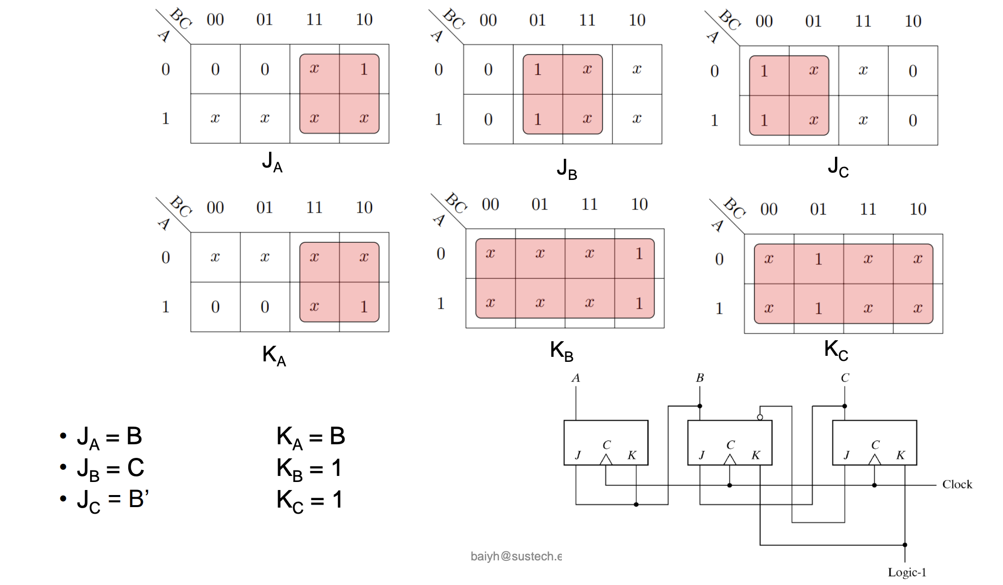
- Derive simplified excitation equations of FFs
- Draw logic diagram
Counters with Unused States
n flops => 2n states
Unused states
States that are not used in specifying the FSM, may be treated as don’tcare conditions or may be assigned specific next states
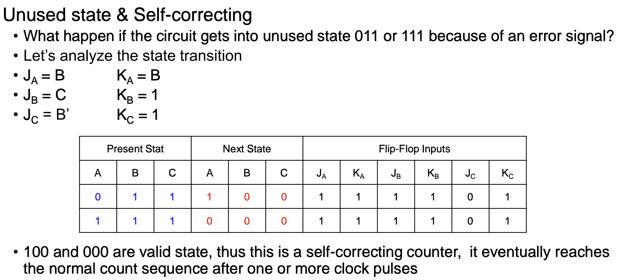
Self-correcting counters
Ensure that when a circuit enter one of its unused states, it eventually goes into one of the valid states after one or more clock pulses so that it can resume normal operation
Analyze the circuit to determine the next state from an unused state after it is designed
J-K Flipflops
At rising edge of clock
$J = K = 0$, Q is unchanged
$J = K = 1$, Q toggles
$J = 1, K = 0$, Q is set to 1
$J = 0, K = 1$, Q is reset to 0
